Aerator - Electrical Install
Electrical Install
Due to the many connections for the MECANUM Wheels, lift motor and drill motor a custom PCB is used to ensure all the connections can be easily made. This PCB can be ordered in the WEBSHOP.
If you have already built the ReP_AL Lawm Mower using the PCB many of the connections will be familiar to you, but there are some major differences so please read the instructions carefully.

Soldering
if you consider yourself a beginner at soldering please spend 5-10 minutes and watch a few soldering videos. Its good time spent and will improve the quality and fun of your build
PCB Components Overview
the following components are required to complete the PCB build and are provided in the PCB Build pack (except the CR2032 Battery)

Set Voltage Regulator
Before connecting the voltage regulator to the PCB board ensure it is outputting 5V. This can be connected to a 12V source (INPUT side) and the adjustment screw turned until 5V output is given.

PCB Components Position
The various Arduino boards and PCB components are arranged as shown in the diagram below. Use the header pins as shown to ensure easy removal of the components should they need to be replaced or serviced.

To ensure the header pins have a good alignment with the PCB and component its best to insert to the header pins into the component. In this case the Arduino MEGA. After inserting the header pins into the Arduino MEGA, push the pin heads into the PCB. Using the Arduino MEGA as a clamp solder the header pins to the PCB. This keeps the pins steady and in perfect position.

The MEGA is positioned on the lower side of the PCB. Use the male header pins to connect the MEGA to the PCB.

TFT Touchscreen Connection
The TFT screen shield uses a separate Arduino MEGA. Before plugging the TFT shield into the MEGA solder 5V, GND and RX/TX wires to the TFT MEGA as shown below. Ensure that the TX is connected to the opposite RX pin on the other board. TX -> RX and RX -> TX.
(If after uploading the code the touchscreen is not responding, see the guide on the Arduino Software page on how to calibrate the screen)

Rain Sensor
the rain sensor is connected to the PCB as shown. Connection points are provided for the 5V, GND and Signal.

Wire Sensor
The wire sensor detects the signal in the perimeter wire fence. The sensor is built as follows and fits inside the recess at the front of the aerator
Ensure the 11P Inductor is soldered directly to the Amplifier. When testing you should get (negative) values of -1000 near the wire and (positive) values of +400 when the mower is outside of the wire (Run the wire test). If your negative and positive values are switched, then either swap the Inductor legs around, or simply swap the wires around on the perimeter transmitter.

Amp and Volt Sensor
The amp and volt sensor plate (3D printed) is used to hold the 2 amp and 1 volt sensors. The amp sensors measure the current to the wheel motors and to the drill motor. The volt sensor measure the overall system voltage of the robot.
The plate is attached to the PCB using the pre drilled holes. M3 screws are used from the back of the PCB to fix the plate (remove MEGA first).
The amp sensors COM line is attached to the Amp1 and Amp2 pins as shown. Any 5V or GND pin can be used to power the sensor. The right hand terminal of the amp sensors are connected to a 12V+ motor pin. The volt sensor is connected to the 12V+ input pin

Wheel Motors
First the motor drivers need to be prepared. 1 Motor drive will power 1 motor. To take advantage of the maximum amps the driver can provide the drivers are bridged. This needs to be done on 5 motor drivers (4 for wheel motors and 1 for the lift mechanism motor)

Please take care when connecting the motor drivers to the PCB. It is very easy to make a wrong connection considering the amount of wires.
A new wheel test is provided on the TFT screen so that each individual wheel motor can be tested for Forwards and Reverse motion.
The 12V source for the wheel motors passed through an amp sensor to monitor if the robot experiences a blockage. Be careful to route the 12V through the correct terminals otherwise a negative amperage may be measured and the wheel block function wont work.
The 12V cooling fans can use the 12V supply for the motor drivers to keep the motor drivers supplied with cooling air.
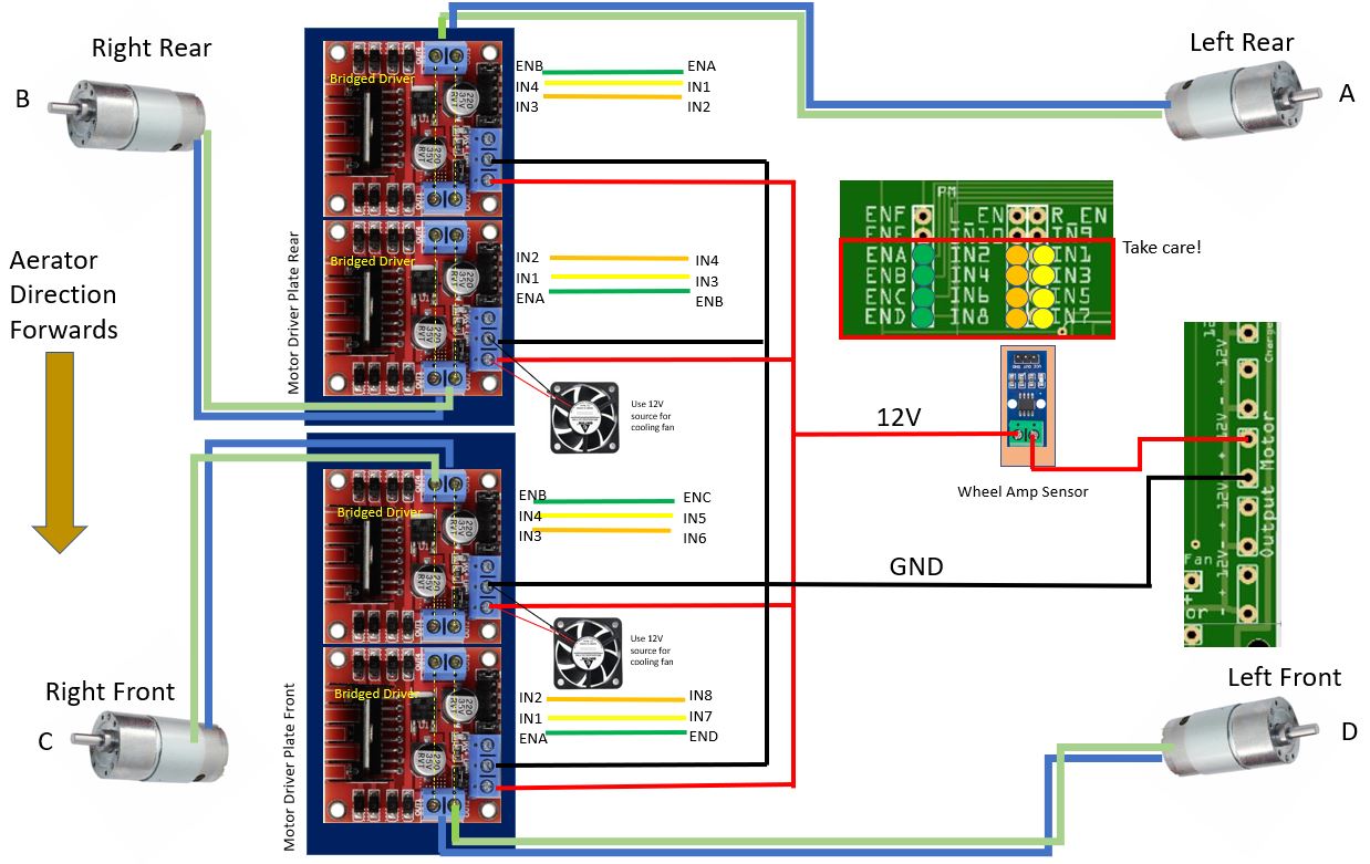
If when testing the motors the rotation is revered, just swap the two wires going to the motor. This will reverse the rotation.

Drill Lift Motor
The drill lift motor is connected to the PCB as shown. Again there is a new test program to check the direction of the lift motor. If the direction is reversed, swap the wires as above for the wheel motors.

Drill Motor
The 12V drill motor is connected as shown. The drill motor 12V source passes through the amp sensor to measure if the drill motor is blocked. This is an important feature when aerating to stop the motor and lift mechanism when the drill is stuck in the earth. A stuck drill reverses the lift motor and ends the aeration cycle.
Again the 12V cooling fan can be connected to the 12V supply and should then turn on when the relay is activated.

Drill Lift End Stop Micro Switches
The end stops detect when the lift mechanism reaches the maximum and minimum positions. This is an important feature and care should be taken to solder them well. without these the drill mechanism will continue to push into the frame of the drill mechanism causing damage.
The end stops can be tested in the test menu.

Main Battery Connection & Charging Pins
The main 12V battery is connected via the power on/off switch which is located on the rear control panel of the robot.
The front charging pins are connected to the 12V+ Charge Pin via the amp sensor and to the negative connector plug of the battery. The Amp sensor is connected to the PCB terminals Sa = signal GND and 5V. The amp sensor detects a charge when the Aerator reaches the charging station and connects with the charging pins. This then shuts down the robot to charge

Sonar Array Connections
3 sonar array modules are used on the front of the aerator. these sonar modules can be turned on or off in the settings using the TFT touchscreen.
I find it easier to group the 5V and GND wires together near the sonar modules and route them to the PCB with just 1 wire for 5V and 1 wire for GND

Compass
The compass orientates the Aerator for the home track cycle. Compass connection pins are provided on the PCB.

PIXHAWK Connections (PIX)
These connections are there ready for the PIXHAWK upgrade which i am working on. For the moment they are there for future use.