330 Monster - Printing & Construction
For the 330 Monster build I used standard PLA. OF course if you want to use other material such as ABS then thats even better. I use PLA to keep it simple and the project open to more builders.
Filament Overview and Part Groupings
This table will give a good overview of the filament required to print the project. It also gives the parts groupings and colours to print. (This is how I print the parts).
The part groupings are designed to get the maximum print uptime by combining similair shapes and colours.

I assume a 1KG filament roll has a length of 320m (officially its 330m but some waste is inevitable).
This gives a requirement of 4 rolls of Black and 2 rolls of Green.
(I will update the table with print times as I collect them)
PRINT SETTINGS
In CURA I used (in General)
- 25-30% Infill on structural parts
- 15% Infill on the Rear Wheels (to keep them light)
- 0.2mm Layer Height
- 1.2mm Line Thickness
- Support only turned on with overhanging parts.
Here a screenshot from my CURA settings. This is the basic start point for all prints which I adjust depending on the type of part (e.g. Wheels reduce to 15% infill)

OVERVIEW OF PARTS
Here are most of the parts labelled so they can be identified and the positions they belong in . All parts are secured with M3 bolts and locking nuts.
Please make sure you read the BUILD ORDER below before starting to construct the mower.


BUILD ORDER! **PLEASE READ**
The previous 330 mower build could be done in almost any order, but the chassis of the 330 monster requires a certain build order for the rear of the mower and swinging hood.. These components should be built as shown so you have access to the hinge points and bolt holes.
1. Rear Cover and Control Panel Door
Firstly solder 40cm of wires to the Rain Sensor (5V, GND and COM). Now push the rain sensor into the Rear Cover LH print.
If you dont do this now it will be very difficult to get the part into the rear cover later on.

The control panel door hinges inside the rear cover using a 2-3mm wire hinge. The control panel door must be inserted before the 2 halves of the rear cover are assembled.
a) Ensure that the parts are well sanded and you have a 90° transition between the rear cover and the control panel door at the hinge points.

b) Insert a 2-3mm wire rod (wire coat hanger will do) into the channel using the access hole provided in the part.

As you feed the wire through the hinge point (Tip: Use a power hand drill) insert the control panel door. Ensure the holes in hinge points are wide enough by pre-inserting the wire into the parts.

Once all the parts are connected with the wire, use M3 bolts to secure the 2 parts together.

I recommended to leave a section of wire protruding from the hinge point (inside the frame at the access hole) in case you ever want to disassemble the parts.
2. Wheel Gaurds and Wheel Motors
Once the wheels are attached or the wheel arch is assembled onto the main chassis it is very difficult to access the screws. (possible but not fun)... Please therefore follow these assembly steps.
a) The rear wheel arches and motors are 1 assembly per side. Press the wheel bearing into the wheel arch (use a small amount of heat and pressure if necessary) and secure it with the bearing clamp.
b) Now attach the wheel motor to the motor bracket. The wheel bracket with wheel motor attached is now attached to the rear wheel arch.

c) Now insert the 15mm diameter metal wheel axle through the bearing and secure to the wheel motor axle with a 6mm set screw. Use loktite on the set screw to prevent it shaking loose!! Test fit the rear wheel to ensure the wheel axle is in the correct position. Dont secure the rear wheel yet until all the other chassis components have been assembled. (The rear wheel blocks all access to the bolt holes inside the rear wheel arch). There are drill templates provided in the STL pack to make the wheel axles.
Completed Assembly - Same for LH and RH

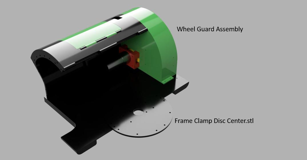
3. Rear Floor.
Attach the rear floor to the completed rear cover and control panel door assembly. (Later access to these screws will be difficult)

Then to give the construction strength add the completed LH Wheel Guard Assembly and the center structural disc
4. Main Cover
The hinge point for the hood runs through the 2 rear covers and needs to be installed before installing both rear wheel arches.
Ensure the parts are well sanded in that area and that the hood has a free movement before installing the wire pin.
Again a 2-3mm wire is pushed through the hinge point (use a cordless drill on a low torque setting to get the pin installed.

5. TFT Assembly
Before you assemble the TFT screen ensure the BMP files are saved onto the micro SD card and inserted into the TFT screens SD slot. Once the screen is installed its not easy to get access to this SD card slot.
Solder the Serial 1 TX and RX wires and 5V and GND wires to the MEGA Board. Label the wires.
After the assembly is complete you wont be able to get to these pins again.
Use the recessed screw holes to assemble the TFT plate to the TFT cradle. The screws need to be flush as these will be sandwiched between the Rear covers!
Once the cradle is secured with the flush screws, attach the plate to the rear of the mower using the M3 bolt holes provided to secure the plate.

The 2 USB jacks and Power Switch can also be installed at this point.
Ensure to wire cable to the power switch before installing it otherwise it can be difficult to reach this area with a soldering iron later.

6. Wheel Gaurd RH Assembly
Now attach the Right Hand Wheel Guard to the assembly

7. Bumper Bars
The bumper bars are a simple construction using springs from a pen


The small micro-switches are available in the store here
Video showing the bumper bar in action (Previous 330 Version). In this test the sonar modules have been disabled in the settings.
8. Front Floor and Facia Assembly
The completed Front Facia and Bumper assembly can now be fixed to the mower along with the other facias, front floor and blade motor clamp.
All thse parts are attached with M3 bolts and M3 safety nuts

The completed assembly looks like this:

9. Sensor Brackets and Blade Controller:
The placement of the compass sensor plate is not so critical as is the tip sensor plate. These brackets need to be screwed to the floor plate after drilling some small pilot holes.
5 Euro cent pieces (or similar size coin/blank) are used as charge plugs. A charge wire is soldered to the back of the 5 Cent piece and fed through the front facia. The wire should be long enough to reach the battery charge connection points.
The wire sensor is placed over the recess in the front floor to allow the inductor to face downwards and detect the wire.
The blade bracket, blade motor driver and blade motor can now be installed.

10. Rear Wheels
To attach the rear wheel you will first need to make the adapters . The rear wheels are then pushed over the adapters and fixed with an M4 bolt through the wheel hub (hole provided) into the wheel axle adapters.

The wheel printed at 15% make them light, but the bolt hole is not strong enough with this infill amount. Use the provided wheel bolt strengtheners printed at 100% infill to give the wheel extra strength in that area and spread the torque to the wheel spokes.

11. Front Wheel Casters & Wheels
The 625ZZ Bearings are pressed into the casters. The casters are then fixed to the frame using flat head M5 bolts through the M5 holes provided at the front of the mower. Spacer washers are required on the M5 bolt to allow the bearings to turn against the frame. An M5 nylon lock nut is used so the M5 bolts dont need to be over tightened. Leave them a little loose to allow free movement of the wheel.

For the front wheels I used 50mm rubber wheels fro the DIY store with an M6 axle. Front wheel STL files are provided but I have not tested them yet...


Rest of the Assembly
From now on the assembly order is not critical and can be assembled as you please following the overview guide at the top of this page.
Please use the electrical install guide to construct the electrical plate before installation