All Robots - Perimeter Wire Module
The perimeter wire transmitter sends the signal through the perimeter wire for the robot to detect the perimeter of the lawn.
The perimeter wire module works for both the Robot Mower and the Aerator, so only 1 module needs to be built to fence in both types of robot.
There are 2 build methods to create the perimeter wire transmitter
A. Perimeter Wire Module Using PCB build pack and WIFI
See the instructions below
B. Perimeter wire Module using standard Arduino components
Both methods will create a working perimeter wire transmitter. The PCB version has the advantage of the circuits being completed by the PCB and it also includes a WIFI module so that the wire transmitter can be switched ON and OFF via the Blynk APP.
If you ordered a mower build pack all the components to make the standard wire module are included.
Instructions for the standard Arduino circuit are at the end of this page.
Build A:
Perimeter Wire Module Using PCB and WIFI
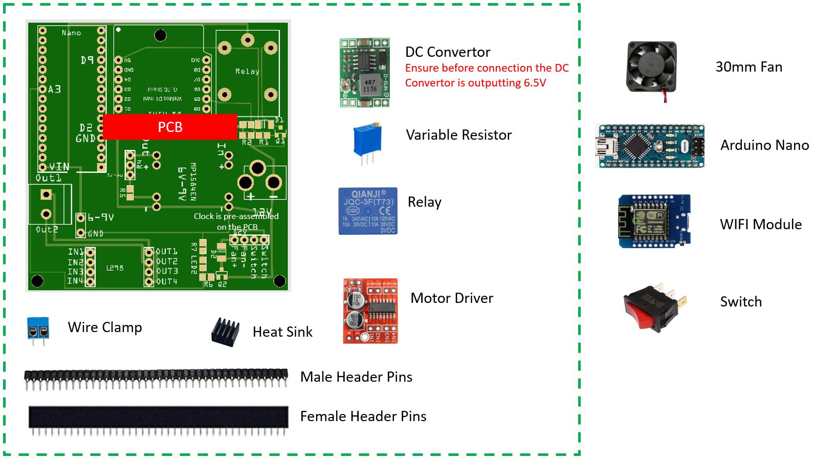
The following parts are included in the Wire Transmitter PCB Bundle. If you ordered option 1 you will receive all the parts shown. If you ordered option 2 you will receive the parts shown in the green box.
Case
A 3D Printed Case for the PCB Perimeter Wire Transmitter can be printed. The STL files are available here:
Perimeter Wire Transmitter PCB.zip

The case and components are fixed with M3 screws (best black).
Creating the BLYNK2.0 APP
Step 1 - Build the BLYNK2.0 APP Wire ON/OFF Button.
The PCB version of the wire transmitter includes the ability to remotely turn the wire ON and OFF.
The Blynk app has been updated to Blank2.0. The free plan on this APP has also changed limiting some of the functions. This tutorial describes how to create a Wire ON/OFF App using the Free Plan on the Blynk2.0 platform. We will need to create 2 separate APPs for the Wire Module APP and for the Mower Controller APP
Step 2 - Create Blynk2.0 Account
Using your web browser create an account on the Blynk2.0 platform. You can choose the Start Free account for now.
Step 3 - Create a new Template

Name this Template ReP AL Wire or whatever you would like to call the APP. Use ESP32 as Hardware and WIFI as connection type.

Step 4 - Create Datastreams
You will now need to create some Datastreams. These are the information streams which will be sent between the APP on your phone and the WEMOSD1 module in the wire transmitter. Choose a Virtual datastream as the type and fill out the streams as shown below with the Name/Alias/Datatype etc... Make sure the Virtual pins are correctly assigned. Once this is setup save the template.

Step 5 - Link Template to Device
Now we need to "+ new device" > "From template" and use the template we just created. Choose the 'ReP AL Wire' Template.


Step 6 - Add ID to the Arduino Code
Once the device is setup you will get the Template_ID and Template_Name for this APP. You need to insert these 2 lines into the Perimeter Wire Transmitter Arduino Code (Wire_WEMOSD1_Blynk_New.ino) which will then be uploaded to the WEMOSD1. Be careful when you copy it as it will copy the whole lines with the command prompts.

Insert the Template_ID and Template_Name into the Arduino Code.

Step 7 - Upload the Code to the Boards (WEMOSD1 and Nano)
Before installing the Arduino Boards on the PCB first upload the code.
The software to upload to the Nano to create the wire signal and the WIFI code for the WeMoS D1 is available on the Arduino Downloads Page here: Once the code is uploaded to the WEMOSD1 it will create a WIFI hotspot for your Smartphone to connect to. Via this WIFI hotspot the WEMOSD1 will link to your smartphone Blynk2.0 App and share the WIFI configuration for your home network.

Step 8 - Create the APP on your phone.
Download the Blynk APP to your smartphone. In the app options bar you have the option to Add a new device ON your APP (you should see the various apps you created in the web browser). The APP may try to connect to your WEMOSD1. If yo power up the WEMOSD1 using a USB cable and allow the app to link to it.

Step 9 - Configure the APP Layout and Datastreams
You now need to add the following elements to the APP screen and configure each element as below.
Button Datastream Wire ON (V0) Label it ON
Button Datastream Wire OFF (V1) Label it OFF
LED Datastream On Confirm LED (V2) Give it a green colour
LED Datastream Off Confirm LED (V3) Give if a red color

If the WEMOSD1 is correctly paired with the smartphone APP, pressing the ON and OFF buttons should give responses on the WEMOSD1 (Wire ON / Wire OFF). This can be viewed in the serial monitor in the Arduino IDE.
The confirmation LED lights should also light according to the ON or OFF commands
Building the Wire PCB
Step 1 - Install Header Pins
The female header pins are soldered in the following positions (in red). this allows the easy removal of a component for whatever reason (damaged, defective etc). Cut the header pins to the right length to fit.
The header pins for the motor driver (6-9V and GND) are not standard spacing. For this section 2 single header pins need to be cut out.
To ensure the header pins are straight its a good idea to use the components as jigs to hold the header pins as you solder them.

Step 2 - Prepare Components
Before installing the DC Step Down module ensure it is outputting approx 6.5V when a 12V input is applied.
Also stick the heat sink to the Motor Driver as shown.

Step 3 - Install Components (Except WIFI)
Install the components as shown. DO NOT INSTALL THE WIFI MODULE UNDER POWER YET. The WIFI module runs with 5V power and we first need to set a 5V source before installing it.
Ensure the INPUT OUTPUT sides of the DC Step down module are correctly aligned.
Be Careful on the Arduino Nano. Some Nanos have extra empty pins so ensure the correct pins are aligned.

Step 4 - Adjust Voltage
Ensure the switch is connected to the PCB otherwise the circuit wont work. Now connect a 12V power supply to the PCB. DO NOT INSTALL THE WIFI MODULE YET
You should measure 6.5V output from the DC Step Down. If this is not 6.5V adjust using the adjustment screw on the DC step down module.
Now measure the voltage to the WIFI module at the 5V and GND pins. By turning the screw on the variable resistor adjust the voltage to the WIFI module to 5V.

Step 5 - Install WIFI Module and re-adjust Voltage
Turn off the power and install the WIFI Module. The WIFI module will add extra resistance to the circuit. Re-measure the voltage on the WIFI 5V and GND pins. Now carefully re-adjust the resistor screw to get 5V at the WIFI module.
If the WIFI module receives less than 5V it wont turn on.

Step 6 - Test and Install Perimeter Wire
The perimeter transmitter should connect to your WIFI network and via the Blynk APP you should be able to turn the module ON and OFF. The LED's on the Blank APP confirm that the signal has been received by the WIFI module and should change accordingly.
The Perimeter wire cable can now be attached the to the plug as shown.

Video of finished Wire Transmitter (PCB Version)
------------------------------------------------------------------------------------------------------------------
Build B:
Perimeter wire Module using standard components.
All the components to complete the standard perimeter wire transmitter are including in the mower build packs.
The software to upload to the UNO to create the wire signal is available on the Arduino Downloads Page here:
The components are connected as shown below.

To turn the motor driver from a double bridge (2 Motors) to a single bridge (i.e. combine the power of both drivers) the motor driver can be bridged like this.

Out1 -> Out4 / Out2 -> Out 3 / IN1 -> IN4 / IN2 -> IN3
This will give more power to the perimeter fence wire.
Case
A 3D Printed Case for the Perimeter Wire Transmitter can be printed. The STL files are available here:
Perimeter Wire Transmitter Case (no PCB).zip
The case and components are fixed with M3 screws (best black).


Testing the Wire Signal
When testing the circuit a long length of wire is required (min 20 meters) otherwise the resistance will be too small for the module to work. I use 3mm diameter, metal stranded, plastic coated wire for the perimeter wire which is available here

See the Main menu for further instructions