All Mowers - WiFi & APP Blynk Legacy
Blynk Legacy Configuration
If you already have a Blynk account you can use the legacy APP otherwise we you need to use the new Blynk IoT 2.0.
How to Create the Blynk Legacy App
To have access to the ReP_AL Lawn Mower via a smartphone we are going to use the Blynk App. With this we can quickly create a smartphone app to talk to the NODEMCU board in the mower:
1. Download and install the Blynk legacy App on your smartphone from the Googe Play or Apple Store. Search for 'Blynk Legacy App'. Once installed create an account.
![]()
2. The Blynk Legacy App works by buying credits for the different types of functional buttons/widgets you use in the APP. In the Blynk App we are going to need roughly 3000 credits. Check how many credits you have. An additonal package of 5000 credits costs €4.99.
We will use the following widgets in the APP
8 Buttons : 200 credits each = 1600 Credits
2 Value Displays : 200 credits each = 400 Credits
6 LED's : 100 credits each = 600 Credits
1 Segmented Switch : 400 credits
Total = 3000 Credits.
3. Create a new project in your smartphone BLYNK app: Call this ReP_AL Mower (or whatever you want), select NodeMCU as the device and WIFI as the connection type.
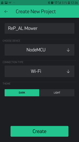
Once the APP is created the APP auth token/code will be sent to you email account address.
You will need this code for the NodeMCU arduino code. This code links the NodeMCU board to this APP.
(If you have more than 1 ReP_AL Mower to control then you will need to create an APP per mower so that each mower has a seperate Auth Token. Once the APP is created it can be duplicated.).
Make sure you have enough credits to buy the buttons/widgets we need (about 3000), then we can start to assemble the APP. This will take around 15-20mins
4. Add 4 buttons to the screen and then resize and position them as shown below. You can add features by pressing the + button on the menu bar. This brings up the 'Widget Box.
Once the widget is added to the APP desktop you can move and resize the buttons by long pressing it and using the frame options provided.


5. We will now label the buttons and assign them 'Virtual Pins'. These virtual pins are the addresses of the buttons in the APP which can be referenced by the Arduino code to carry out actions. By tapping on the button you will be presented with the buttons attributes.
- In OUTPUT select 'Virtual Pin' by scrolling the menu, then select the correct Virtual Pin number for each button.


- For all buttons keep the button Type as Push
- Select the button colour as in the pictures below
- For all buttons remove the word Button by adding a space to the box.
- The buttons can be labelled by changing the text in the ON/OFF Labels box


The 4 buttons should have the following attributes.
| Button Position | Virtual Pin | Colour | Label |
| Top Left | V2 | Red | Pause / Stop |
| Top Right | V0 | Orange/Yellow | Quick Start |
| Bottom Left | V10 | White | Exit Dock |
| Bottom Right | V1 | Blue | Go to Dock |
It is important that the virtual pins are assigned correctly to each APP button otherwise the APP will not work correctly or behave strange.
(Colour and Text is up to you, but it's best to stick to the instructions here before you start to customise it)
6. Now add 2 Value Display and 6 LED features/widgets to the APP and arrange them as in the screenshots below:

Give the new widgets the following attributes by clicking on the widget and modifying the settings.
| Button Type | Virtual Pin | Label (OFF) |
| Value Display | V5 | Loops |
| Value Display | V3 | Volts |
| LED | V7 | Mowing |
| LED | V11 | Compass |
| LED | V9 | Tracking |
| LED | V8 | Docked |
| LED | V12 | Charging |
| LED | V6 | Parked |
7. Add 4 more buttons to the APP and position them as shown. These buttons will allow the mower to be steered manually..! :)

Give these 4 buttons the following attributes:
| Button | Virtual Pin | Label (OFF) |
| Top Button | V13 | FWD |
| Lower Button | V14 | REV |
| Left Button | V15 | 《 |
| Right Button | V16 | 》 |
10. Finally we need to add a segmented switch to the APP (you must use Code V6.7 onwards). Again position the switch as shown in the screenshot and give it the following attributes.


Output: V4
Labelling
Option 1 - Auto #
Option 2 - Auto @
Option 3 - Auto | |
Option 4 - Manuel
( # = random mowing @ = Spiral | | = parallel )
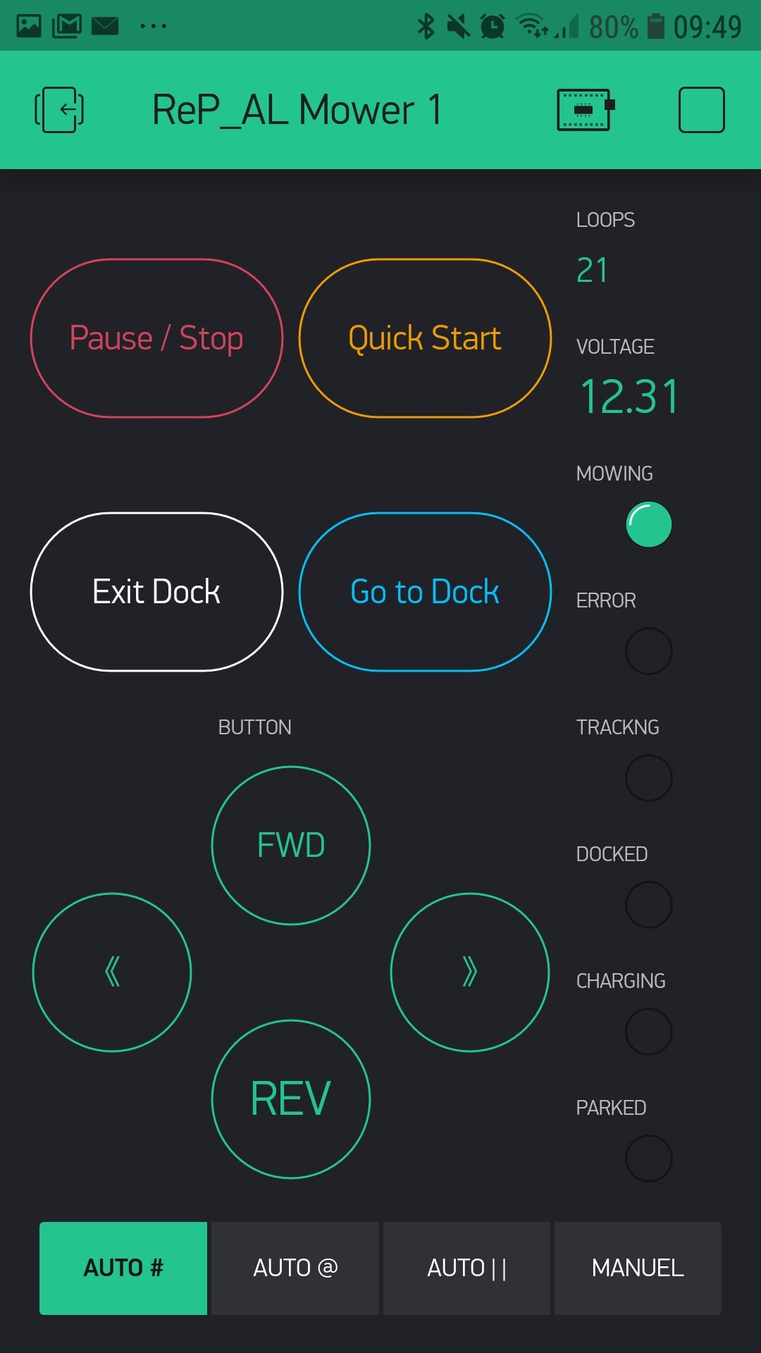
The APP is now complete and should look exactly like this when running.
Pressing the play button in the BLYNK menu will start the APP. The APP will now start to look for the connection to the NodeMCU. The APP works through the BLYNK server, so it can be controlled from your smartphone anywhere you have a data connection (WIFI or Cell phone provider data). Yes that means you can control your mower from anywhere.....! :)
Now the NodeMCU needs to be configured with the code to connect to the Blynk APP
WIFI Settings Tab
To use this feature ensure you are using the Code V9.5 or higher.
This feature will allow certain settings of the mower (Sonar, Compass etc) to be remotely controlled via the Blynk APP. You may need to purchase additional BLYNK credits to add all the Widgets needed for this APP feature.
1. Insert a new tab into your BLYNK APP by going to the Widget Box and selecting Tabs. (The Tab is the band of options you see at the top of the screen like a tab in Excel).
2. Name your new Tab Settings. (You can name Tabs as you like)
3. Add 15 Segmented Switches to the Blynk screen. Each segmented switch should have 2 options on it. Label each segmented switch as shown in the screen shot below:

(screen scrolled down)

I grouped the buttons by changing the colours. (e.g. White for Alarms)
4. Give the buttons the following Virtual Pins by editing the settings of that button

| Button | Virtual Pin |
| Compass | V20 |
| Heading Hold | V21 |
| GYRO | V22 |
| Sonar 1 | V24 |
| Sonar 2 | V25 |
| Sonar 3 | V26 |
| Bumper | V29 |
| GPS | V33 |
| Angle Sensor | V34 |
| Tip Sensor | V35 |
| Wheel Amp | V36 |
| Alarm 1 | V30 |
| Alarm 2 | V31 |
| Alarm 3 | V32 |
| Sync | V23 |
The buttons do as they are labelled and turn ON or OFF that sensor / feature.
When the mower is docked the settings will be periodically synced to the WIFI APP.
The Sync button will manually sync the BLYNK app to the mower settings. (The BLYNK app will start with all the buttons in the OFF position which is not synced to the actual settings of the mower. Press the sync button when starting the APP). This will not work is the mower is running.
Adding NODEMCU capability to the ARDUINO IDE
As the NODEMCU board is not in the standard list of boards to choose from in the Arduino boards menu, we need to add the NODEMCU & ESP functionality to the Arduino IDE. If you already have the ability to upload to NodeMCU boards you can slip this section.
1. In the Arduino IDE, settings menu add this URL address to the "Additional Boards Manager URL's" box, then press OK. This will give the Arduino IDE the download address to install the necessary software to communicate with the NodeMCU board.
http://arduino.esp8266.com/stable/package_esp8266com_index.json

2. To complete the download of the NODEMCU software go to the Board: menu in the Arduino IDE and select Boards Manager.
In the next window type ESP in the search field.

The ESP8266 should appear in the window.

Install the latest version of the ESP board software.
Once the download is completed you should now have NodeMCU 1.0 as an additional option in the boards menu.

Uploading the Blynk Code to the NodeMCU:
1. Download the NodeMCU code from the Arduino Code Page. The NODEMCU code is within the main MOWERX.X code package. Use the NodeMCU Blank_Old code
2. Open the NodeMCU code and update the "WLAN Name" network (name of your WiFi network take care with case sensitivity) "password" and "App Key Code" (Auth Code- that you received by email when you created the APP).
This information will allow you NodeMCU to connect to your home network and link to the Blynk Cloud server and your smartphone APP.

4. Ensure all the blynk libraries are installed. The BLYNK libraries are included in the libraries used folder from the GITHUB site so you should have all the libraries required already.
Alternatively you can download the BLYNK libraries from the BLYNK website if you want to ensure you are using the same libraries.
5. Now Upload the Arduino code to your NodeMCU board using the Arduino IDE.
The Nodemcu board should now connect to your WiFi network and to the BLYNK server using the Auth Code.
You can check that the NodeMCU is connecting properly by viewing the serial monitor of the NodeMCU.